In the post-war period, several types of shortwave (HF) radio stations were used in the Czechoslovak army. In addition to the Germans, who remained in our territory after the Wehrmacht, the British ( WS19) a sovietske ( RBM1 and RBM-5). Their common disadvantage was that they were represented only in relatively small numbers, insufficient for military needs. Therefore, the development of a new, modern radio station for the needs of the army was started. The basic requirement was a range of at least 30 km day and night, the possibility of operation by telegraphy and telephony and simple operation.
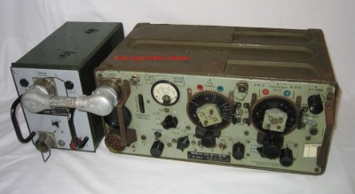
The design team chose the British radio station WS 19 as a model, took over the cast chassis from the German design school, and the use of a crystal-controlled frequency control panel contributed to the solution, which greatly simplified operation. The development of WS19 began in 1941. The radio station was designed as a receiver-transmitter in a transceiver connection, which means that some parts are used for both the receiver and the transmitter. For this reason, it is possible to operate the radio station only in simplex mode, i.e. the radio station receives or transmits signals. The WS19 scale was relatively coarse, which complicated tuning to the operating frequency. The use of a crystal-controlled frequency control panel in RM31 with a tuning step of 5 kHz simplifies and refines tuning. To tune the radio station to one of the 800 channels, it was enough to switch 4 switches and select the appropriate type of operation (telegraphy or telephony). The most modern tubes, American seven-pin with battery power, were used as components. The only exception was the end tube of the transmitter, RL15A, which was of Czechoslovak construction. The original American tubes were replaced by Czechoslovak copies. However, these suffered from imperfectly mastered technology and were therefore relatively faulty. The most common disorder was the microphone, which manifested itself as a sharp ringing sound when you tap the tube or the whole radio station. The circuit solution was very modern for its time. 30 crystals were enough to select one of the 800 operating frequencies (channels). Another crystal was designed to fine-tune the receiver and transmitter, and the last was built into the receiver's IF amplifier, where it allowed the bandwidth of the received band to be changed. The change in bandwidth made it possible to suppress interference, especially during telegraph operation, and at that time practically only separate receivers and receivers of large radio stations were equipped with it. There were also some changes during production, the most striking was the replacement of the measuring device for tuning the antenna in the antenna part with a light bulb.
Version RM31P was the most widespread version, the operator consisted of 3 men. It was divided into 3 loads. It served to connect motorized rifle regiments with the division and as a personal radio station for all-army commanders of higher units. Own radio station, manual dynamo for transmitter with stand and 2.4 V/10 Ah battery for powering the receiver, vibration converter, antenna part and accessories (antennas, spare parts). The operation of the radio station with a rod antenna was also possible while moving, but all members of the operator were connected to each other by power cables. These could be disconnected by a simple jerk without damage, which happened very often during transfers, especially at night.
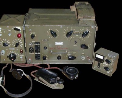
Technical data of the basic radio station: Operating frequency range 2,000 to 5,995 MHz Transmitter power 6 W for A1 and 1.5 for A2, A3 Receiver sensitivity 3 µV for A2, A3 and 1 µV for A1 Types of operation A1 - unmodulated telegraphy A2 - modulated telegraphy (1 kHz) A3 - amplitude modulated telephony Weight of individual loads load I. 18 kg 350 x 230 x 300 mm burden II. 22 kg 365 x 440 x 170 mm burden III.21.5 kg 230 x 540 x 260 mm The accessories consisted of: handset, microphone, headphones, telegraph key with strap for attachment to the foot, measuring device for checking the electronics in the radio station, spare tubes, insert into the microphone, rod antenna 1.8 m, rod antenna 4.8 m and wire dipole 2 x 2 + 7 m, version RM31A aj 2 x 8 + 4 + 7 m.
RM31 with antenna part and measuring device for electronic control
The radio station was produced in versions: RM31P - infantry RM31A - automobile RM31S - for self-propelled guns RM31T - for command tanks, was supplemented by a radio station RM31-50 operating in the VHF band
Radio range:
fónia day - 15 to 25 km night - 4 to 7 km
telegraphy day - 50 to 60 km night - 20 to 30 km
The other versions consisted of its own radio station, rotary converter, antenna part, two batteries 5NKN45 and accessories. They were mounted according to the type of mobile device for which they were intended. The antenna part and the radio itself were the same for all versions.
The radio station was used from the beginning of the 50's until the end of the 60's. One of the largest deployments of radio stations in "combat" use was during the flood on the Danube in 1954, when soldiers provided flood reports directly from the Danube. The radio stations were placed on 6 local inflatable boats of the "Dinghy" type anchored by the shore and the staff was under a tent built on this boat. From the mid-60s, infantry and later automobile and tank versions began to get into the hands of radio amateurs through Zväzarm, where they were used until the early 80's and sporadically, especially lovers of nostalgia are still used. At the same time, radio amateurs routinely communicated with these radio stations throughout Europe.
Literature: History of the Liaison Force, VHU Prague 2007 Handbook for non-commissioned officers of the liaison army, Prague 1962 Brief data on links used in ČSLA, Prague 1965
Rádiostanica WS19 Mk2
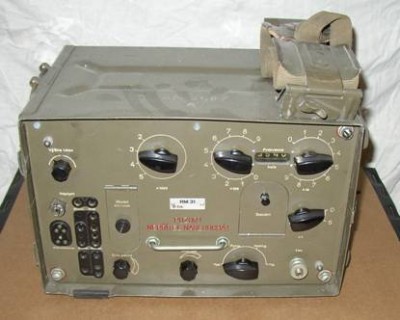
Hlavný blok RM31
Anténny diel a aku prijímača
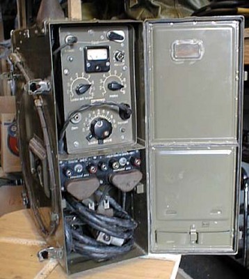
Prevádzková zostava RM31
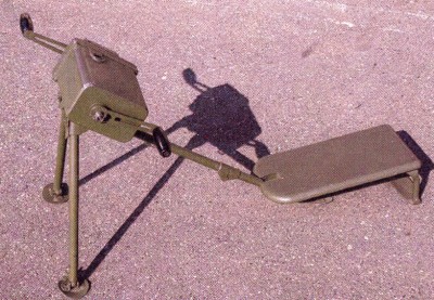
Ručné dynamo k RM31 (Býk)
URL : https://www.valka.cz/CZK-RM-31-Supertana-radiostanice-t80974#296582
Version : 0
To supplement the picture of the RM31 installation in the Škoda 973 car, which according to the film "If a Thousand Clarinets" was given the name Babeta and in the next picture the stand for the RM31 to be built into the GAZ 69
URL : https://www.valka.cz/CZK-RM-31-Supertana-radiostanice-t80974#299579
Version : 0
Reklama
In the picture is a collage with an embedded prijímačom R3 has affected the anténneho dielu. Long for the msm couldn't zistiť what is the voľný priestor designed. Bol pre R3 ako záložný prijímač. For anténnym dielom boli two sets of akumulátorov 5NKN10 pre R3.
Source: own zbierka.
URL : https://www.valka.cz/CZK-RM-31-Supertana-radiostanice-t80974#317276
Version : 0
Code označenie RM-31 in JANUARY bolo SUPERTÁŇA.
URL : https://www.valka.cz/CZK-RM-31-Supertana-radiostanice-t80974#360902
Version : 0
Diskuse
Is not a simplex continuous transmission or reception without the possibility of switching? Not applicable for communication link more poloduplex?.
URL : https://www.valka.cz/CZK-RM-31-Supertana-radiostanice-t80974#317357
Version : 0
Reklama
Nie simplex is, or počúvam, or vysielam. Poloduplex is prevádzka rovnaká ako simplex, but with the team rozdielom that prijímam on inej frekvencii ako vysielam. Full duplex is súčasný income aj vysielanie, each on inej frekvencii. In small sieťach is simplex najbežnejší kind of prevádzky. Poloduplex requires substantially väčšiu discipline and fit sa especially on radio direction, I mean spojenie two stations. To sa station navzájom do not disturb..
URL : https://www.valka.cz/CZK-RM-31-Supertana-radiostanice-t80974#317360
Version : 0
I beg to differ. Poloduplex is alternating traffic on one frequency, the duplex is simultaneous operation at two frequencies. Discipline poloduplexních networks maintains control station. It's true that I'm on the radio, he served in the years 1971-73; since then, things may have changed..
URL : https://www.valka.cz/CZK-RM-31-Supertana-radiostanice-t80974#317379
Version : 0
We got sa bit to rozporov in definíciách Ako poloduplexné, possibly with a mechanical duplexom are referred to spravidla armádne rádiostanice type R-105. This is a contradiction compared to the general zaužívaným definíciám, where sipl = simple, but the aj one from the act frekvencie on ktorej running prevádzka. Duplex is from the word duplicate = two, I mean two pracovné frekvencie. Ako dôkaz prikladám kópiu from the book "Land mobile radio services" from autorov ing. E. Linhart, ing. J. Climate, CSc, ing. And Kotora, ing. In. Mašek, ing. To. Olbrich vintage record known to man NADAS 1982. It matches definície používajú aj authors "Sredstva svjazi passažirskich samoletov", doc. inż. dr. L. Gvozddjak "Fundamentals of electrical engineering transmission and spracovania messages. (1962) "Rádiokomunikační regulations" Geneva 1971 and with a little neskromnosti aj I think in summon rigoróznej work "Bezdrôtová komunikácia". Team sa we don't want dotknúť some autorov ktorí používajú other delenie. Only on the margo semestrálnej work, there is ako simlex referred to actually radio vysielanie, which is commonly referred to as "Jednosmerné" and is yet one of the foriem simplex..
URL : https://www.valka.cz/CZK-RM-31-Supertana-radiostanice-t80974#317396
Version : 0
Good day,
I asked for help, if someone please know where it would be possible to get or download military prirucky Joint-21-3 1961 and them similar. Of the time this is complete manual for radio RM-31A (operation, description, repair), and dale on prijimace R3, R4 and depend then the RS-41 Trinec.
Thanks for the types on the indianszavinacxsmailteckacom
Thank You, Peter.
URL : https://www.valka.cz/CZK-RM-31-Supertana-radiostanice-t80974#352824
Version : 0
Peter, answer me on mail miro.hornik(at)gmail.com and we'll send You what I have.73 Miro om3cu.
URL : https://www.valka.cz/CZK-RM-31-Supertana-radiostanice-t80974#352838
Version : 0
Hi,
thanks for the quote. I sent You an e-mail to the specified address.
With best regards,
Peter O..
URL : https://www.valka.cz/CZK-RM-31-Supertana-radiostanice-t80974#353709
Version : 0
On prehlidce in Prague gave the order to nahozeni tank and then to the check-out....started have just a simple tank...disorder radio RM-31..
URL : https://www.valka.cz/CZK-RM-31-Supertana-radiostanice-t80974#567885
Version : 0
Join us
We believe that there are people with different interests and experiences who could contribute their knowledge and ideas. If you love military history and have experience in historical research, writing articles, editing text, moderating, creating images, graphics or videos, or simply have a desire to contribute to our unique system, you can join us and help us create content that will be interesting and beneficial to other readers.